The Metallurgy of Torque: Analyzing the PENN Slammer III Chassis
Update on Jan. 15, 2026, 7:49 a.m.
In the domain of mechanical engineering applied to saltwater environments, the primary adversary is not merely the target species, but the physics of torque and the chemistry of corrosion. The PENN Slammer III represents a specific approach to these challenges: the prioritization of structural rigidity over mass reduction. When a rotational force is applied to a winch system under heavy load—such as a spinning reel battling a pelagic fish—the chassis is subjected to intense torsional stress. If the housing flexes even by fractions of a millimeter, the internal gear mesh becomes misaligned. This misalignment concentrates stress on the gear teeth tips, leading to premature wear or catastrophic failure. The Slammer III serves as a case study in using high-density metallic alloys to eliminate this flex, creating a rigid envelope for the transmission system.
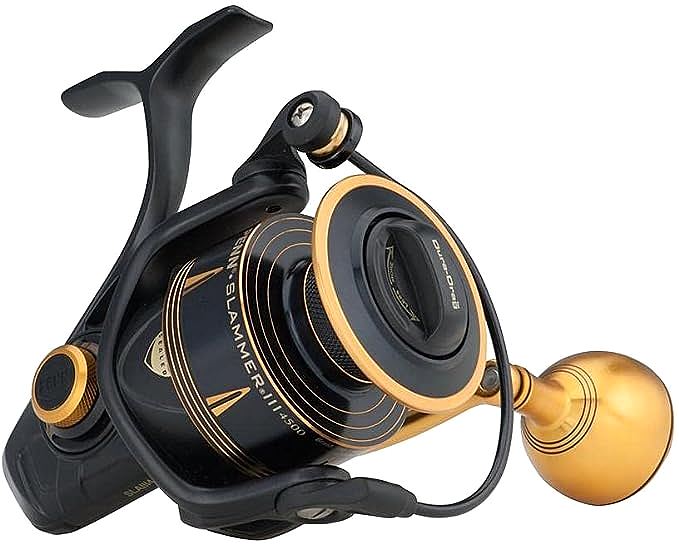
The device constructs its “Full Metal Body” from a die-cast aluminum alloy. While significantly heavier than carbon-composite or graphite alternatives, aluminum provides a high modulus of elasticity. This ensures that the distance between the main gear axis and the pinion gear axis remains constant, regardless of the drag pressure applied. This analysis deconstructs the machine’s core components, focusing on the material science that defines its operation.
Structural Rigidity: The Physics of the Full Metal Chassis
The fundamental requirement of any heavy-duty transmission housing is dimensional stability. In the context of the Slammer III, the “Full Metal Body, sideplate, and rotor” specification indicates a unified material approach designed to resist deformation. When the rotor is subjected to line tension, it acts as a lever arm, exerting a bending moment on the main shaft and the reel body stem.
Graphite or plastic-reinforced composites, while lightweight, exhibit a lower yield strength. Under peak loads—such as the 30+ pounds of drag force capable in the Slammer III series—a composite stem can deflect. This deflection alters the angle of the rotor relative to the spool, causing uneven line lay and increasing friction on the main shaft. By utilizing aluminum, the Slammer III maintains orthogonality between moving parts. The metal acts as a rigid non-deformable frame. This is particularly critical for the sideplate, which houses the main gear bearings. Any flex in the sideplate would allow the main gear to shift laterally, reducing the contact area with the pinion gear and risking “gear stripping” where the teeth shear off due to point-loading.
CNC Transmission Topology
Inside the aluminum housing lies the powertrain, driven by “CNC Gear technology.” This terminology refers to the manufacturing process: Computer Numerical Control machining. Unlike die-cast gears, which are formed by pouring molten metal into a mold, CNC gears are cut from a solid billet of metal.
In the Slammer III, the main gear is machined from brass. Brass is chosen for its tribological properties; it offers a degree of self-lubrication and ductility that allows it to mesh smoothly with stainless steel pinion gears without excessive wear. The CNC process ensures superior concentricity and tooth profile accuracy compared to casting. Cast gears often suffer from porosity (microscopic air bubbles) and surface irregularities that create noise and vibration. Machined gears possess a uniform grain structure, enhancing their fatigue strength. The interaction between the brass main gear and the stainless steel pinion is a classic engineering pairing, balancing hardness (steel) with durability and smoothness (brass).
Thermodynamics of the Dura-Drag Composite
A drag system is, fundamentally, a clutch mechanism designed to slip at a predetermined torque threshold. This slipping converts kinetic energy (the fish pulling line) into thermal energy (heat). The efficiency of a drag system is defined by its ability to manage this heat without experiencing “fade”—a reduction in friction coefficient due to temperature rise—or “stick-slip,” which manifests as jerky line release.
The Slammer III employs the “Dura-Drag” material, a proprietary composite originally developed for automotive transmission applications. Unlike traditional felt washers which can compress and burn, or standard carbon fiber which is effective but can be abrasive, Dura-Drag utilizes a phenolic resin matrix impregnated into a carbon weave.
From a thermodynamic standpoint, this material is chemically stable at high temperatures. The weave structure creates a microscopic texture that maintains a consistent coefficient of friction even when saturated with heat. Furthermore, the stack of washers is sealed. This isolation is crucial because the introduction of saltwater into a drag stack changes the fluid dynamics between washers, leading to unpredictable friction spikes. The “Sealed Slammer drag system” ensures that the friction environment remains chemically consistent, dictated only by the drag grease and the washer material, not by external contaminants.
The Mass-Durability Trade-off
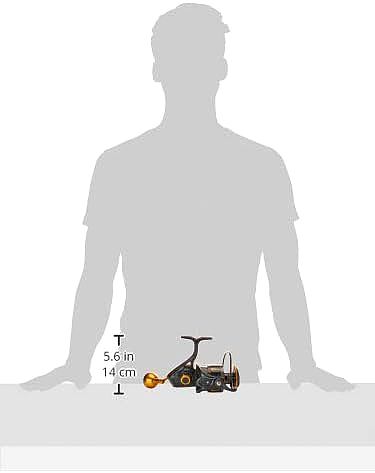
The engineering decision to prioritize metal construction and heavy-duty gears results in a specific physical characteristic: mass. The Slammer III is measurably heavier than competitors utilizing composite bodies. For example, the 6500 size weighs significantly more than a similar-sized graphite reel. This is not an inefficiency but a calculated trade-off. Mass in the rotor adds rotational inertia, requiring more force to start spinning but aiding in smooth cranking once in motion. The weight is the physical manifestation of the material density required to achieve the target structural rigidity.
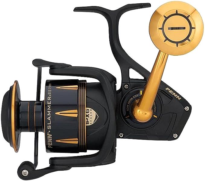
Hydrostatic Barriers: Engineering IPX6 Compliance
Corrosion in marine environments is galvanic and pervasive. The Slammer III addresses this via an IPX6 sealing protocol. The “6” rating indicates resistance to high-pressure water jets, implying that the reel can withstand heavy spray and washdowns. This is achieved through a labyrinth of hydrostatic barriers.
The sealing architecture involves rubber gaskets at critical ingress points: the drag knob, the main shaft entry into the rotor, the handle entry points, and the sideplate-to-body interface. These seals function by creating a compression interference fit. However, sealing a rotating shaft presents a tribological challenge. The seal must be tight enough to exclude water but loose enough to minimize rotational friction. The engineering solution often involves lip seals that utilize the internal pressure or the shape of the lip to maintain contact without excessive drag. The Slammer III’s design accepts a certain degree of rotational resistance (heavier handle turn) as the cost of this hermetic security.
Bearing Architecture and Load Paths
The reel utilizes a “6+1 stainless steel bearing system.” The placement of these bearings defines the load path. The main shaft is supported by bearings to reduce friction during vertical oscillation, while the pinion gear is supported by bearings to handle the radial loads from the rotor. The “+1” refers to the instant anti-reverse bearing, a roller clutch that prevents the handle from turning backward. This component is critical for hook setting, as it must lock instantaneously under shock loads. In the Slammer III, this clutch is often reinforced or supplemented with a backup mechanical dog (in larger sizes) to prevent failure if the roller bearing slips under extreme torque.
Kinetic Energy Transfer at the Interface
The interface between the operator and the machine is the handle assembly. The Slammer III features a machined aluminum handle arm that threads directly into the main gear. This “direct drive” design eliminates the play found in through-shaft designs (where a hexagonal shaft passes through the gear). By removing this tolerance stack-up, the transfer of kinetic energy from the angler’s hand to the gear train is direct and lossless. The large knob (aluminum or EVA) provides a surface area for applying torque, allowing the user to leverage the mechanical advantage of the gear train effectively.

Conclusion: The Engineering Outlook
The PENN Slammer III is an exercise in mechanical resilience. Its design rejects the modern trend toward weight reduction in favor of absolute structural integrity. The use of a full aluminum chassis, CNC-machined brass gearing, and a sealed drag system utilizing automotive-grade friction materials positions it as a high-torque implement for harsh environments. The physics of its construction dictate that it will be heavier and potentially have higher start-up inertia than composite rivals, but these are the necessary byproducts of a machine built to maintain precise gear alignment under loads that would deform lesser materials. It is a device engineered for the management of extreme physical forces.